You’ve printed someone else’s file. Here’s how to make the next one
yours.
CHAPTERS / 01
Choose your route
Start with the one thing your object has to get right.
Take the thing you want to make and finish this sentence. “I’ll
know it worked when…” If the answer is “it looks like my frog,”
start with a mesh. If the answer is “my pencil slides into it,”
start with dimensions.
New terms on this page+
CAD
Computer-aided design. You describe a part with shapes,
dimensions and operations such as cutting a hole.
Parametric
A named value controls part of the shape. Change the hole
diameter once and all three pencil holes update.
FDM / FFF
The printing process your Bambu uses. A hot nozzle lays melted
filament down in lines, one layer at a time.
Mesh
A skin made from small flat faces. In an STL, those faces are
triangles.
Slicer
Software that turns the model into paths the printer can
follow. Bambu Studio is your slicer here.
01
Text → mesh
Meshy
For characters, reliefs and invented shapes. Describe the
silhouette, then inspect the back, feet and underside.
Expect to choose between several attempts.
02
Image → mesh
Tripo or Meshy
For a specific silhouette. Use a clean reference with the
whole subject in frame. Tripo accepts multiple views.
Matching front, side and rear views give the model evidence
about hidden surfaces.
03
Words → CAD code
Claude + OpenSCAD or CadQuery
For spacers, organizers and holes with known sizes. The AI
drafts a short recipe. You run it locally, read its
dimensions and keep it to change later.
04
Guided sketch → solid
Autodesk Fusion
For a part you want to shape on screen. Sketch one face,
constrain its size and extrude it. Fusion’s Assistant can
help with modeling commands. Availability varies by release
and account.
Give the AI something a pair of calipers could check.
Pick up the real object it has to fit. Measure its widest point
twice. Sketch a top view on paper and mark which face will sit on
the bed. Those two minutes usually buy more than another paragraph
of adjectives.
Name the job
Say what the part holds or depicts, how it sits, and what must
remain open. For a pencil holder, the floor must close and the
bores must open upward.
Set dimensions and units
Give the outside width, depth and height in millimetres. Name
the critical opening and the amount of play you want. Separate
fixed dimensions from the sizes the AI can choose.
Describe the build direction
Ask for a flat contact face at Z = 0, connected features and
gently sloped undersides. A bridge spans two known supports.
An overhang reaches out from one side.
Ask for a checkable deliverable
For CAD, ask for editable code with named parameters and an
expected bounding box. For a mesh, ask for one continuous
object, then inspect the plain untextured model.
MODEL BRIEF
Write OpenSCAD for a 54 × 22 × 30 mm desktop pencil block. Use
three vertical blind bores in one row, 16 mm apart. My pencil
measures 8 mm across its widest point. Start with 0.3 mm
clearance per side. Leave a 3 mm floor. Put the flat base on Z =
0. Expose the dimensions as named parameters and explain how to
print a short fit coupon.
“Blind” means the hole ends inside the part. Here the first bore
diameter is 8 + 2 × 0.3 = 8.6 mm. That arithmetic gives a test
size. Your printed hole gets the final vote.
Get from a prompt to a file you can actually change.
For a sculpture
In Meshy, generate from text or upload your reference. In Tripo,
use image-to-3D for a sketch or set of aligned views. Pick a
result by its outline in solid view. A painted groove that
disappears when you turn off the texture will disappear in a
single-color print, too.
Look under the belly and between the legs. Rotate all the way
around. Reject detached toes and hollow-looking slivers early.
Export a copy as STL, keeping the original mesh so you can undo a
repair.
For a measured part
Install OpenSCAD for your computer. When it opens, choose New. The
editor is where your recipe goes, and the preview shows what it
builds.
Get OpenSCAD ↗
Paste the brief into a coding assistant such as Claude. Ask it to
draft OpenSCAD and explain each parameter. Read the proposed
sizes, then paste the modeling code into OpenSCAD. Press F5 to
preview. Change one size and check the right feature moves. Press
F6 to render, read the console, then use File → Export → Export as
STL. Keep the .scad file beside it.
If the assistant returns broken code, give it the exact error and
the smallest failing example. Ask it to explain which solid it
subtracted. For complex edge treatments or a STEP handoff,
CadQuery offers Python operations such as boxes, workplanes and
holes. Keep its Python source with the export.
For a part you draw on screen
In Fusion, start a sketch on the XY plane. Draw a rectangle,
dimension its sides, finish the sketch and extrude it. Sketch a
circle on top, dimension its diameter and position, then cut down
to the required depth. Ask the Assistant how to constrain a
drifting circle or find a command. Inspect every feature and
measure the result before exporting STEP for Studio.
Catch missing walls, broken surfaces and impossible fits.
Save a copy before repairing. An automated fix can close the slot
you needed or fuse parts that should move. After each change,
compare the opening, outline and dimensions against your brief.
The slicer flags non-manifold edges+
A solid’s skin must enclose a volume. For a simple closed
triangle mesh, two faces meet at every edge. A gap, an
internal face or shells touching along one edge can confuse
the inside/outside test. Meshy offers a printability check and
automatic repair. In Blender, use the 3D Print Toolbox checks
to locate the fault. Try Make Manifold on a copy. Compare the
repaired outline, re-export and slice again.
A wall or detail disappears+
Zoom into Preview and count actual extrusion paths. A wall
near a single line width may vanish or become fragile. Read
the outer-wall line width from your active process profile.
Two or three paths are a useful first design target for a
handled detail. Enlarge a thin feature in the source and
re-slice. More infill cannot restore an absent perimeter.
The piece starts in midair+
Scrub upward until the new island first appears. A nozzle
cannot lay a free-floating dot. Rotate onto a broader face,
slope the underside, split the part at a flat joint, or add
removable supports. Steeper slopes depend on cooling, material
and speed. A 45° slope from vertical is a test starting point.
The parts should slide but jam+
Clearance is the intentional space between parts. Tolerance is
the variation you can accept. A 10 mm pin in a 10.6 mm bore
has 0.3 mm nominal space on each side. Print a short coupon
with several gaps using the same orientation, filament and
profile. Select the smallest gap that gives the motion you
want.
The part is tiny or enormous+
STL carries coordinates without a unit label. Read the
bounding box in Studio. A 2-inch sketch interpreted as 2 mm is
25.4 times too small. Set one known dimension with uniform
scaling, verify all three axes, and correct the source units
for the next export.
The repaired mesh still has odd pockets+
Run intersection and thickness checks as well as the solid
check. A watertight mesh can intersect itself or contain a
cavity you never asked for. Inspect layer cross-sections. When
the repair changes the intended shape, regenerate the sculpt
or rebuild the critical area as CAD.
Read the plastic paths before you commit the filament.
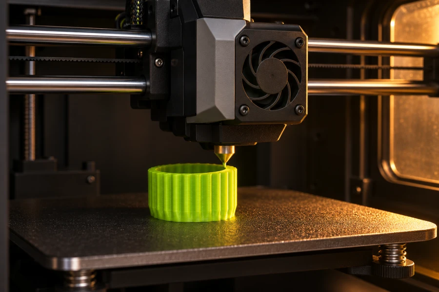
FIG. 04 / DEPOSITION ON THE BUILD PLATE
Load your own machine profile
Open Bambu Studio and start a new project. Choose the exact
printer, installed nozzle, physical plate and loaded filament.
Bambu’s current family spans machines including the A2L and
P2S. Bambu also announced H3C in November 2026. The profile
for the machine on your desk determines the available bed and
settings.
Import and read the dimensions
On Prepare, drag in your STL or STEP. Studio also accepts OBJ
and 3MF. A project 3MF can carry process settings, so check
the printer and material again after opening one. Select the
object and read its X, Y and Z sizes in Scale.
Choose the face and supports
Use Lay on Face to place the broad flat bottom on the bed.
Start with the matching standard process preset. Enable
supports if the design needs them. Tree supports can reach
isolated details. Check whether you can actually remove them
through the opening.
Slice, then read the layers
Click Slice plate. In Preview, use the line-type color scheme
and vertical layer slider. Isolate layer one to check contact,
then scrub to the first hole, bridge and roof. Look for
missing walls, floating islands and supports trapped inside.
Read the time and material estimates. Return to Prepare for
edits and slice again.
Save and send
Save the project as 3MF so you keep your orientation and
settings. For a connected printer, choose Print plate, confirm
the destination and spool mapping, then send. For removable
media, export the sliced plate file for that printer and
select it on the machine. Watch the first layer stick across
the full footprint.
BAMBU STUDIO / SLICE STUDY
Read a real layer.
Seven cross-sections from a Bambu Studio slice of the default
vessel. Slide between them to see where the solid floor
becomes a hollow body.
LAYER 1 / 350
0.2 mm
The footprint
The bottom touches the plate across a filled patch.
Outer wallInner wallFill & skin
A1 mini · 0.4 mm nozzle · 0.20 mm Standard · Bambu PLA Basic.
Paths extracted from the slice. Colors identify feature groups.
Use a small first print to answer one real question.
Make the cheapest print that can answer your question. For a
fitted hole, keep the real bore diameter and print only the bottom
few millimetres. Shrinking the entire part changes the question.
Let the part cool
Remove the part according to your build plate’s directions.
Trim loose strands before measuring. Measure the opening at
more than one height and orientation.
Compare a prediction with the part
Write down the requested diameter, modeled diameter and
measured result. Try the actual pencil or pin. If it binds
only at the base, inspect for a widened first layer before
increasing the whole gap.
Change one parameter
Open the source and change the clearance or thicken one wall.
Save a new revision, re-export, then slice with the same
material and profile. Record what changed so the next print
teaches you something.
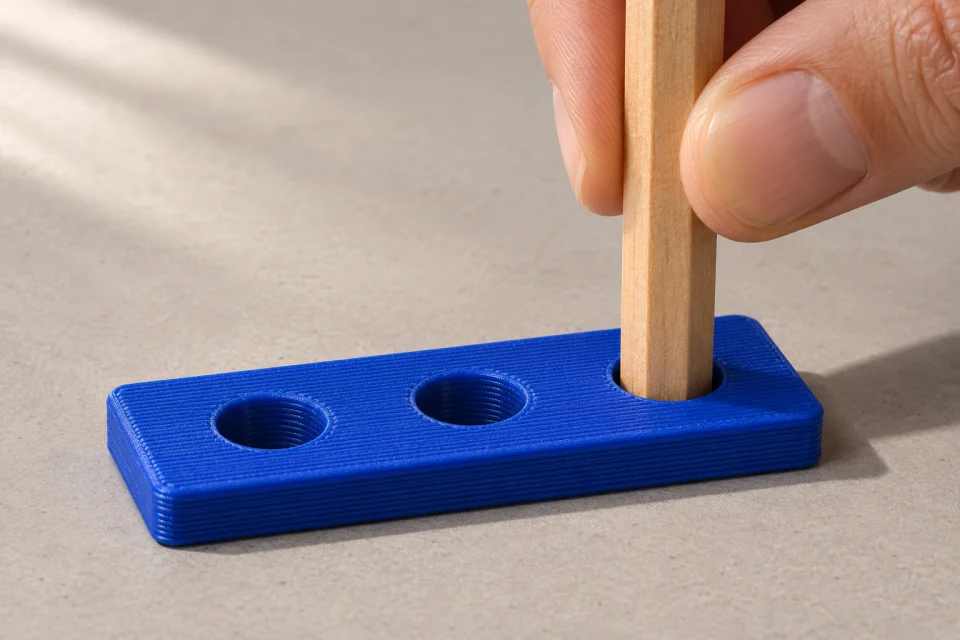
FIG. 05 / TRY THE FIT BEFORE PRINTING THE FULL PART
Your finish line
The block holds the real pencil. The frog sits without wobbling.
The vessel has a continuous floor. Pick a check you can perform on
the cooled print, and keep the source and 3MF that passed it.